WorkActive Build
The Filament Fridge
A 14-cubic-foot wine cabinet rebuilt as an autonomous thermoelectric dehumidifier for 3D-printing filament storage.
It’s important to understand the point of this build. 3D printing uses rolls of plastic filament, which it melts and then feeds through a nozzle to create the model sent from the slicer software. Though it varies by plastic type, filament is hygroscopic—it wants to absorb water from the air. Wet filament doesn’t print correctly, so drying filament and keeping it dry during storage matters. The problem compounds as the collection grows.
I’d recently outgrown the “standard” methods of dry filament storage: plastic cereal containers and sealed storage totes outfitted with piles of desiccant beads to pull moisture from the air inside. Then the beads have to be dried in the oven once they reach capacity. The result is a constant cycle of tracking what is stored in which box and scheduling filament-drying sessions—usually with more than ten hours of lead time—before a print can begin.
I’d gotten frustrated with all of it. In my never-ending quest to remove friction from my life, I decided it was time to go big and solve the problem wholly. I had an idea of how to do that, so I started looking for large, sealed boxes that no one wanted.
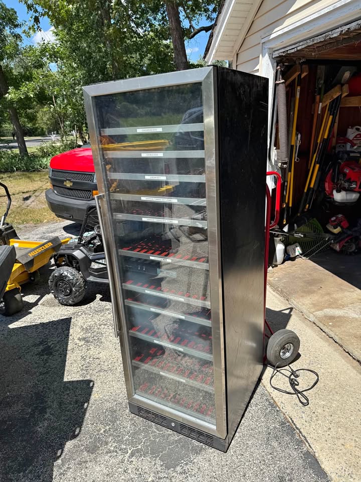
The Filament Fridge began as a dead 166-bottle Danby wine cabinet from Facebook Marketplace (“free, you transport”). Its compressor ran, its sealed system had already been opened to atmosphere, and it could no longer cool. What remained was unusually useful: a tall, gasketed, glass-fronted enclosure with shelves sized for a substantial filament inventory, factory lighting worth preserving, and enough hidden volume behind the inner wall to build a second machine inside it.
The project is a conversion, not a repair. I am replacing the failed refrigeration loop with a thermoelectric dehumidifier, autonomous controls, separated airflow paths, and a sealed PETG barrier. The cabinet is roughly 14 cubic feet—large enough that every easy answer borrowed from a desktop dry box stops being easy.
This page records the design and build state as of August 31, 2026. The machine was electrically alive and controlling correctly; final mechanical assembly and commissioning remained underway.
Features
· Dry, not cold. The target is filament below 20% relative humidity in a cabinet at or near room temperature; cold is the mechanism, dryness is the product, and the commissioning measurement is the pulldown curve rather than a temperature reading.
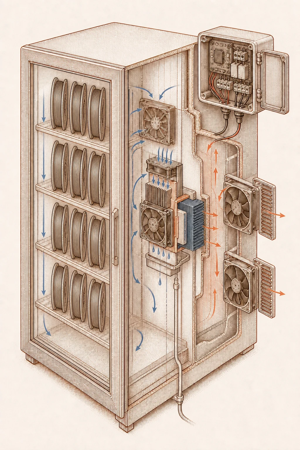
· Two loops that share heat and nothing else. Independent dry-side and warm-side air circuits meet only at the thermoelectric stack; condensed water runs down vertical fins to a funnel and out to the house drain.
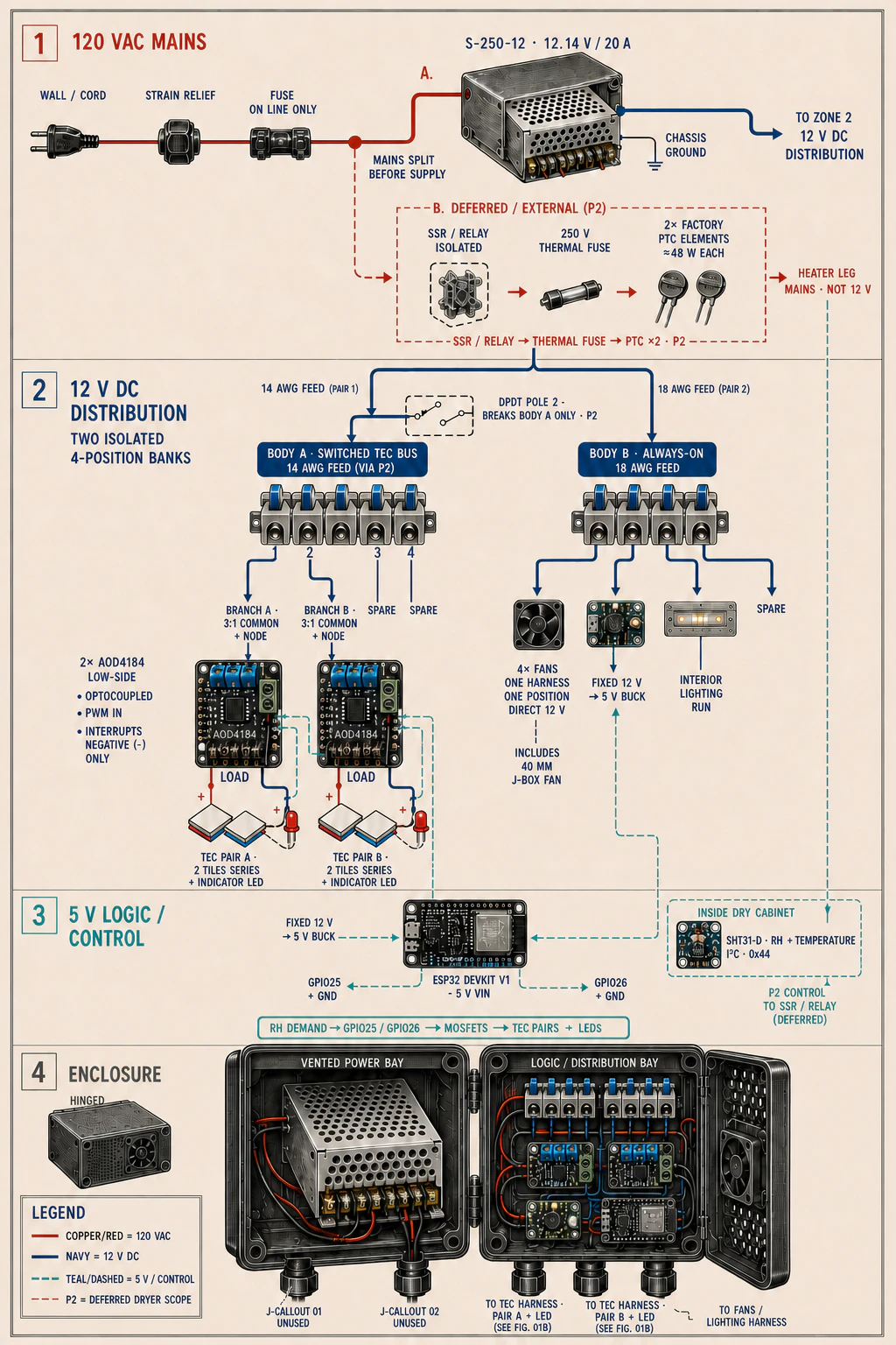
· A budgeted thermoelectric cartridge. Four TEC1-12706 tiles in two independently switched series pairs draw roughly 4.8 amps and 58 watts at the 12-volt supply — inside the 20-amp supply’s real budget, against the roughly 19–20 amps four parallel tiles would demand.
· A controller that does not need the network. The ESP32 runs the loop locally against an SHT31-D sensor with a 30%-on / 20%-off humidity deadband. Home Assistant observes, graphs, and exposes controls; it is not the thermostat, and loss of Wi-Fi cannot stop dehumidification.
· Fails toward off. The controller boots with both TEC gates off, fails toward off when sensor data goes stale, and runs its watchdog on elapsed time. ESPHome’s default network reboot timeouts are disabled — a network outage is exactly when autonomy matters.
· Provenance is an engineering property. Every value in the build record is tagged as measured on this machine, ruled with the part in hand, or unverified proposal — a discipline that caught gasket dimensions wrong in every important direction and a lost condition that had hardened into a prohibition.
· Reversible until measurement earns permanence. The PETG barrier is trial-fitted, drilled, and populated before its perimeter bead goes down; baffles and fan spacers stay deliberately swappable so plateau data decides which pieces earn their restriction.
The correction that organized the build
The most important design decision was one sentence:
The centerpiece of this build is a hand-built Peltier dehumidifier. Put simply, it makes one surface cold enough to cross the dew point. Water condenses there, leaves the air, and drains away. Cold is the mechanism; dryness is the product.
That distinction sounds obvious after it is stated. Before it was stated, the project had spent five sessions optimizing the side effect. The specification treated lower cabinet temperature as success, even though cold filament can collect moisture when it leaves the enclosure and enters warmer room air. Once the variable was corrected, temperature became something to observe and limit rather than maximize.
The target is a cabinet at or near room temperature that holds filament below 20% relative humidity. The real commissioning measurement is the pulldown curve. A smooth decline means the drying path is doing useful work. A high, flat plateau points first to leakage—the door gasket, panel perimeter, or another air path—not automatically to insufficient thermoelectric capacity.
Two loops that share heat and nothing else
The system has two independent air circuits separated by the cabinet’s rear barrier. Only heat crosses between them. The centerpiece is a series of thermoelectric coolers (TECs)—ceramic tiles that, when energized, get very cold on one side and very hot on the other.
On the dry side, a 40 mm fan drives cabinet air down through a short plenum and across two 120 × 69 × 36 mm cold heatsinks that pull cold temperatures from the TECs. The sinks’ straight fins stand vertically so condensed water has an uninterrupted path downward. A 120 mm fan returns the dried air to the filament storage cabinet. Below the sinks, a rectangular funnel catches condensate and carries it out to the house drain.
On the warm side, room air enters the open bottom of the rear pocket, traverses a 150 × 120 mm crosscut heatsink that pulls heat from the TECs, and exits through a plenum, two serial 120 mm fan positions, and the rear grate. The fans sit in series because the limiting problem is pressure through fin channels, not free-air fan count. The second fan, baffle depth, and spacer length remain deliberately swappable so plateau data can decide which pieces earn their restriction.
The original cabinet’s dead condenser radiators occupied both ends of that warm path. Leaving them in place would have put three fin banks in series while only one performed useful heat exchange. They were removed before the new barrier went in, restoring the full intake and exhaust path.
The thermoelectric cartridge
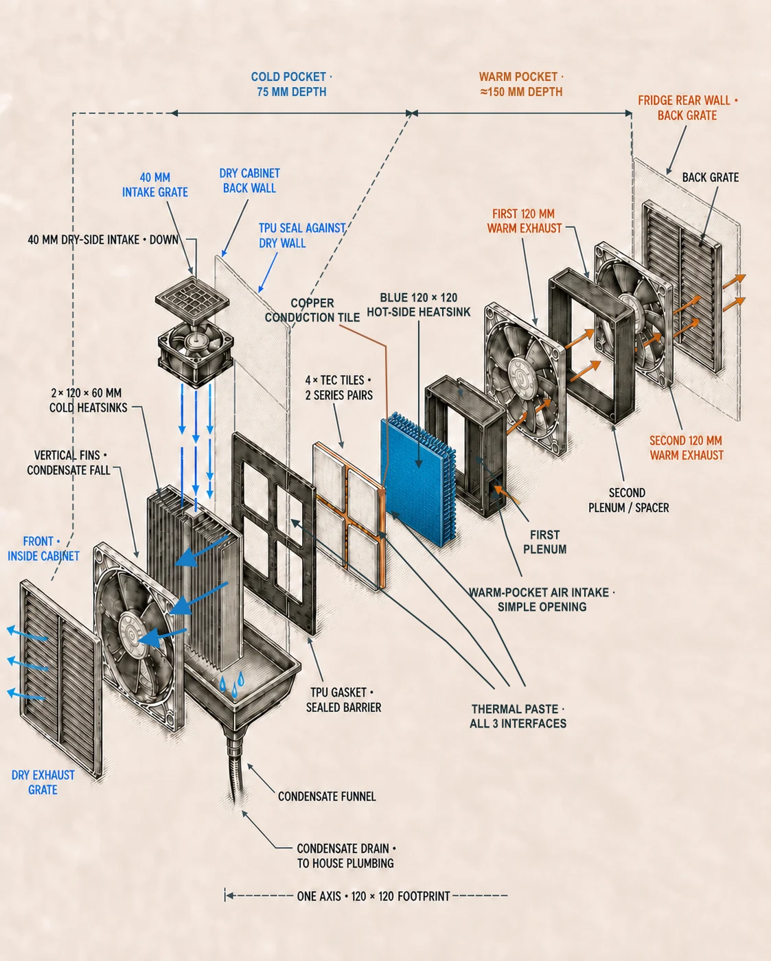
The thermal stack uses four TEC1-12706 tiles arranged as two independently switched series pairs. At a 12-volt supply, each tile sees roughly 6 volts. The four-tile arrangement distributes the cold face across more of the sink while remaining inside the 20-amp supply’s real budget: approximately 4.8 amps and 58 watts for the tiles rather than the roughly 19–20 amps four parallel tiles would demand.
From the cabinet outward, the stack is:
- Two straight-fin cold heatsinks, aligned vertically for drainage.
- A 200 × 200 × 3.25 mm TPU gasket with four tile windows, forming the thermal break and sealed flange.
- Four 40 × 40 × 3.8 mm TEC tiles in two series pairs.
- A 2 mm copper conduction tile.
- One blue 150 × 120 × 20 mm hot-side heatsink.
Thermal paste fills all three conductive interfaces. The copper is not decorative and no longer serves as a generic “spreader”; it compensates for the hot sink’s thin base and gives the TEC array a continuous conduction surface. The TPU prevents the hot and cold hardware from forming a thermal short around the tiles.
The first version of this assembly pressed the hot side into the fin ends of a liquid-cooling radiator. That was line contact masquerading as a heat exchanger. The redesign replaced it with the ordinary—and correct—thermoelectric stack: flat ceramic faces clamped between flat-base heatsinks. It was a substantial rework, but preserving a clever housing around the wrong thermal interface would only have made the failure more expensive.
A controller that does not need the network
An ESP32 control unit running ESPHome reads an SHT31-D humidity and temperature sensor inside the dry cabinet and switches the two TEC pairs through separate MOSFET gates. Humidity demand uses a deadband rather than chattering at one threshold. An adjustable duty window provides a second control layer if the target humidity proves physically unreachable under continuous demand. Currently, the duty window turns the TECs on once the cabinet reaches 30% relative humidity and off once it drops below 20%.
Home Assistant observes the cabinet, graphs it, and exposes controls. It is not the thermostat. The control loop runs on the ESP32, and loss of Wi-Fi or Home Assistant cannot stop dehumidification.
That separation was proven necessary on the bench. ESPHome’s default API and Wi-Fi behavior rebooted the board after fifteen minutes without a client. In this machine, repeated network-triggered restarts would clear demand and interrupt every duty window during the exact outage when autonomy mattered. Both reboot timeouts are now disabled. The controller boots with both TEC gates off, fails toward off when sensor data becomes stale, and runs its watchdog using elapsed time rather than inferred timer ticks.
The build record is part of the machine
The project’s specification grew into more than a parts list because physical builds punish unmarked certainty. Values in the record are tagged by where they came from: a measurement on this machine, a ruling I made with the part in my hands, or an unverified model-authored proposal. That distinction caught several errors after they had begun to look like settled engineering.
The gasket dimensions were once inherited from an unverified proposal and were wrong in every important direction. A conditional statement I made about retaining the refrigerant loop lost its condition and survived for five sessions as an absolute prohibition. The barrier panel was briefly assigned structural duties it never needed because a printed T-bar carries the load. A permitted segmented print became an instruction to segment before I had made that decision.
Those are not clerical anecdotes. Each one changed what would be cut, printed, purchased, or permanently sealed. The build therefore treats provenance and reversibility as engineering properties. The PETG barrier is trial-fitted, drilled, and populated before its perimeter bead goes down because sealing it is a point of no return. Swappable baffles and fan spacers wait for measurements. Unknowns remain labeled as unknowns instead of being rounded into confidence by repetition.
Where it stood on August 31
The AC input was fused and continuity-checked. The 12-volt supply was live and trimmed to 12.14 volts. The fan and TEC lever buses were landed and short-checked; all four fans ran in their labeled directions; all four TEC tiles registered rather than reading open. The dead condenser loop had been removed without refrigerant or oil discharge, leaving the warm pocket clear.
The ESP32 had flashed successfully, joined the network, and completed over-the-air updates. The SHT31-D enumerated at address 0x44, produced a stable ambient baseline around 65% RH, and drove the full humidity-to-demand-to-GPIO chain. Breathing on the sensor moved the reading from 65.11% to 88.96% in one 30-second cycle—a crude test, but a useful end-to-end receipt that the measurement was physical rather than a floating input.
The remaining work was mechanical and empirical: print and install the barrier T-bar, cut and seal the two-sheet PETG wall, assemble the final TEC cartridge and condensate path, mount the control hardware in the rear-access enclosure, and let the closed cabinet produce a real pulldown curve. That curve—not a spreadsheet estimate—would decide whether the system was leakage-limited, heatsink-limited, or material-limited.
The Filament Fridge is a workshop project, but it is also a compact statement of how I build systems generally: separate the loops, keep the controller close to the process, fail toward the safe state, make reversible choices until measurement earns permanence, and let the machine veto the document.
Written about this project
Provenance
- Published
- 2026-09-01 — generated from commit history, not maintained by hand